

DJI SDK
Drone
Receives the calculated flight path and provides mission commands, telemetry and an FPV video feed.
DGAC / DSNA · Android field application
An application dedicated to drone-based flight inspection of ILS and VOR navigation aids. From mission preparation to analysis, UFIS brings together the tools teams need in the field.
01 / Understanding flight inspection
Flight inspection uses airborne measurements to check the quality and accuracy of the radio signals that guide aircraft. It helps ensure that the guidance received by pilots matches the aircraft’s actual position.
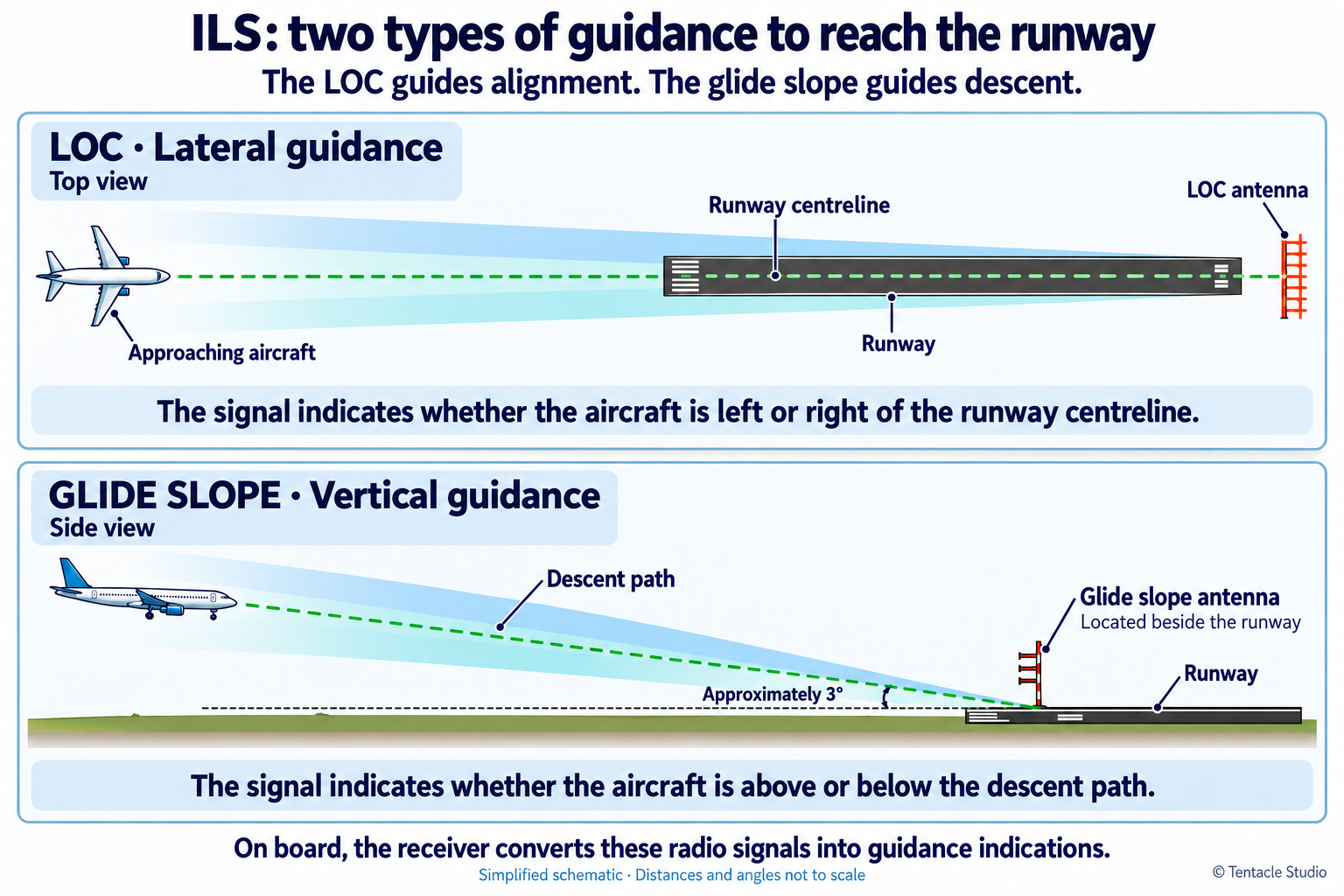
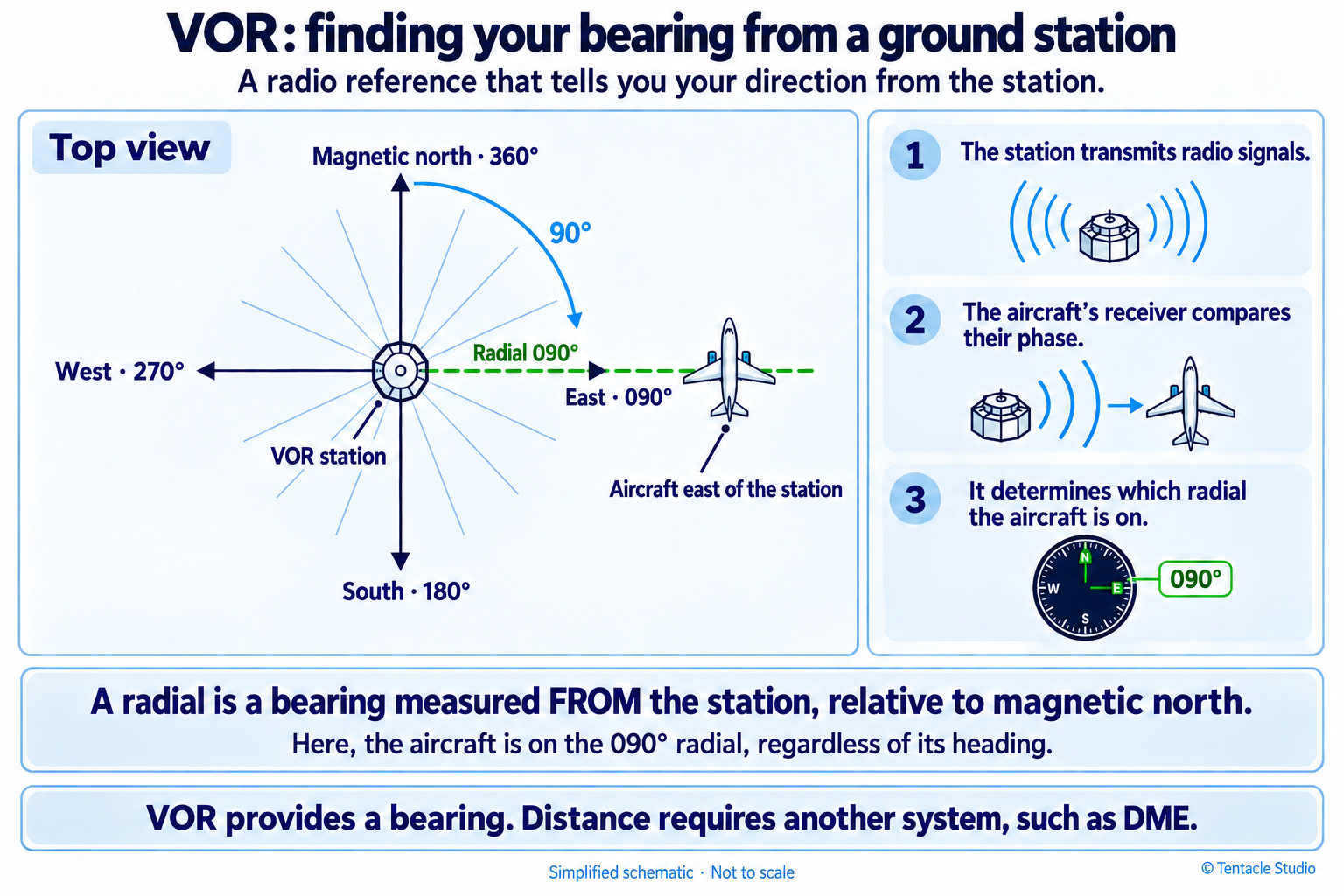
Even in the GPS era, aircraft use ground-based radio navigation aids to navigate and land. Near a runway, the ILS provides two complementary references: the localizer (LOC) guides the aircraft along the runway centreline, while the glide slope (GLIDE) indicates the descent path to follow. The VOR acts as a radio beacon, allowing the aircraft to determine its bearing relative to a ground station.
These installations undergo regular inspections, traditionally carried out by specially equipped aircraft. The UFIS (Unmanned Flight Inspection System) project aims to perform some of these measurements with a drone close to the installations. For suitable inspections, drones can simplify deployment and reduce the need for flight inspection aircraft, helping to save fuel.
The challenge goes beyond flying a drone near an antenna. A lightweight measurement system, called the “rover”, must be carried on board, and the drone must fly through defined points or along specific paths around the installation. Each radio measurement must be associated with a precise position and time so that it can be interpreted. A ground station, called the “base”, provides a reference for differential satellite positioning (GNSS / RTK), which can achieve centimetre-level accuracy when conditions allow.
The UFIS tablet application supports teams throughout this process: preparing flight paths, configuring equipment, monitoring the flight and measurements in real time, then analysing and exporting the results. It connects the equipment in the field with the data needed to inspect the installations.
02 / Inside the application
Charts, mapping, flight parameters and receiver data: an interface designed to move from the overall picture to an individual measurement.
Scroll horizontally through the screenshots or use the arrow keys.
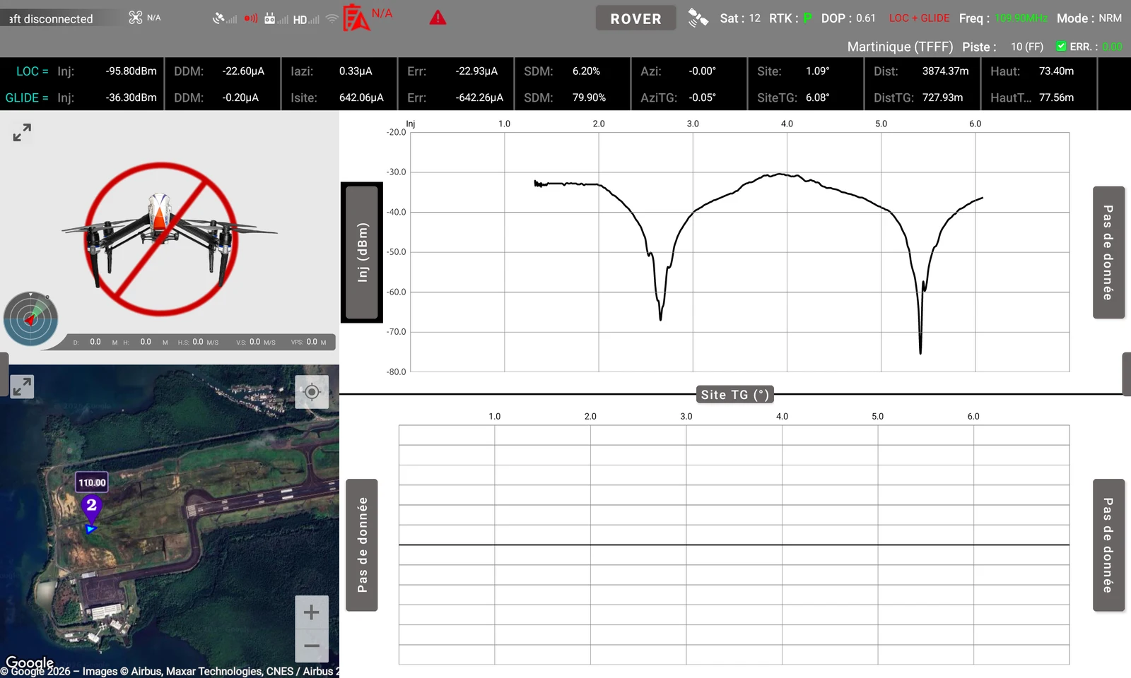
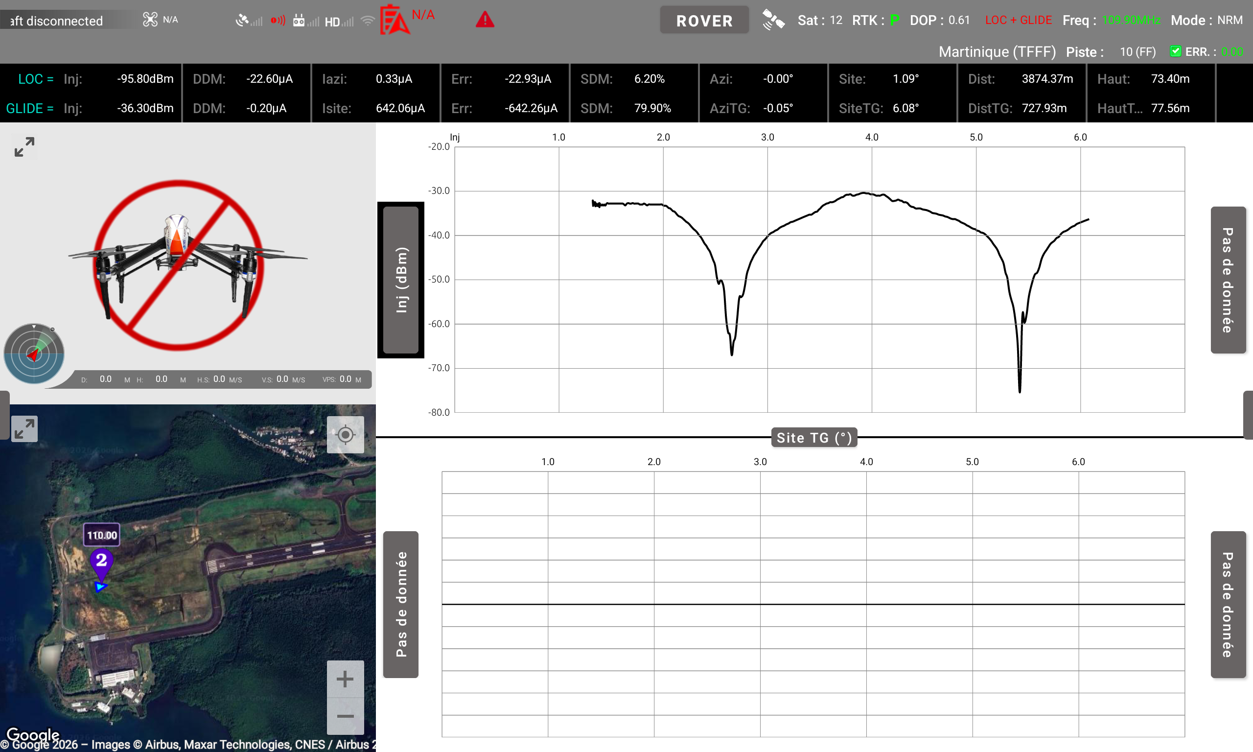
Drone and rover information, real-time measurements, charts, mapping and the FPV feed (unavailable here because no drone is connected) on a single screen.
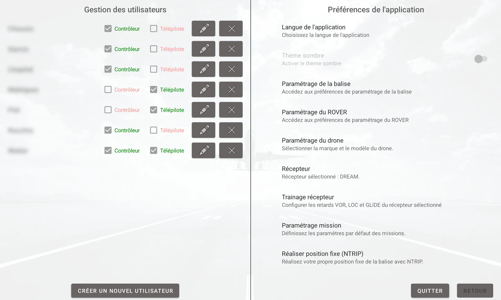
Controller and remote pilot roles, equipment preferences and default mission settings.
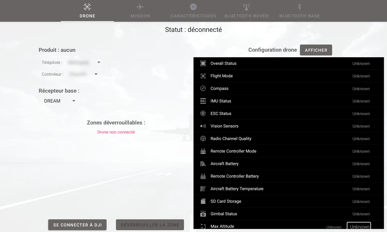
Remote pilot, controller and receiver selection, DJI connection and drone system status.
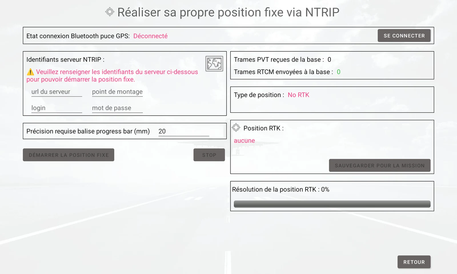
NTRIP server and required accuracy settings, PVT and RTCM frame monitoring, and saving the RTK position for the mission.
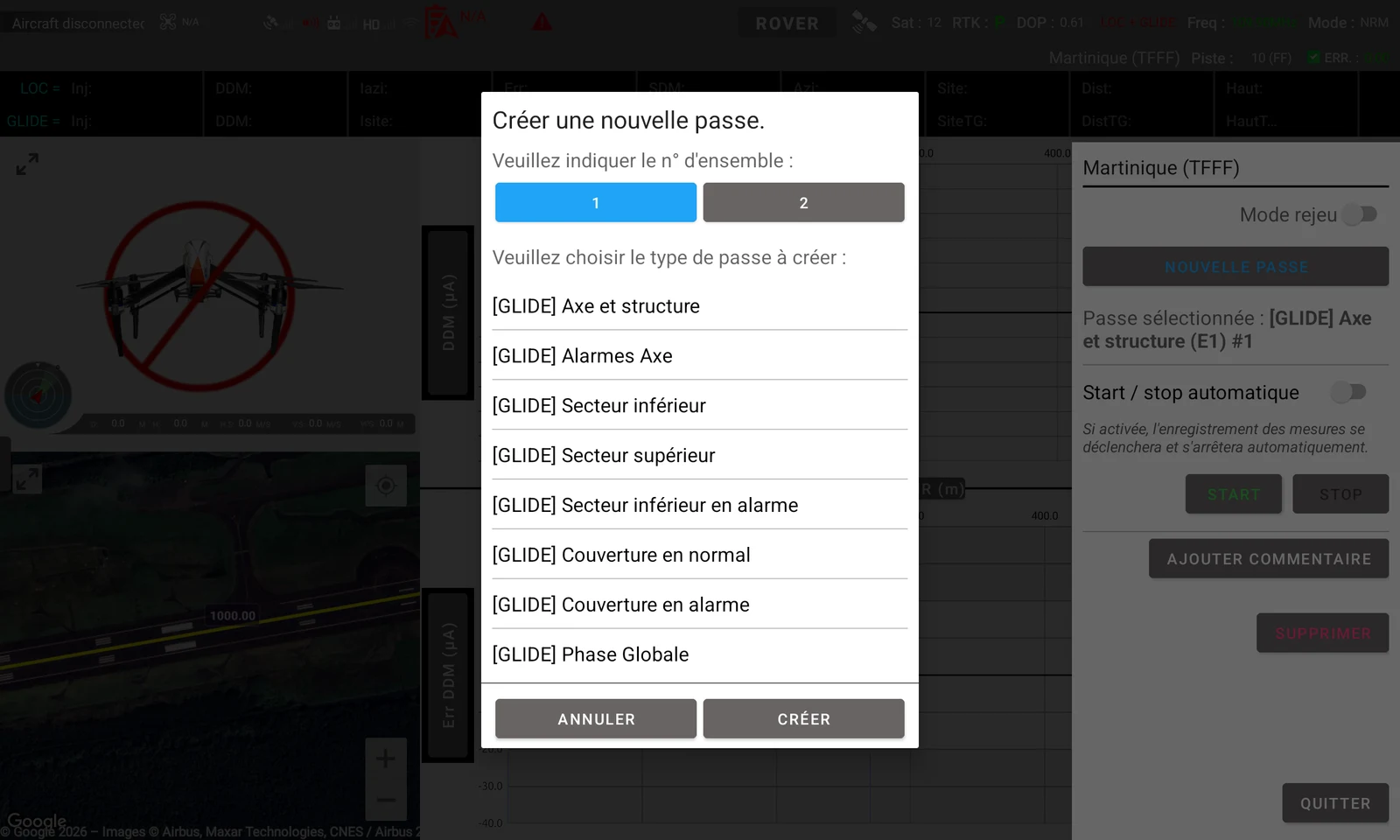
Creating a new pass by choosing from the full range of available pass types.
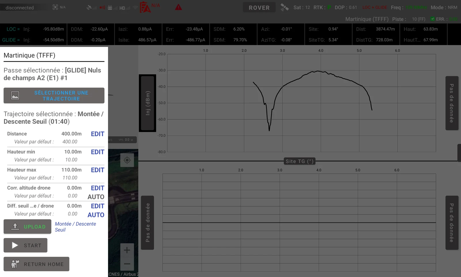
A climb / descent example: distance, heights and altitude corrections before uploading to the drone.
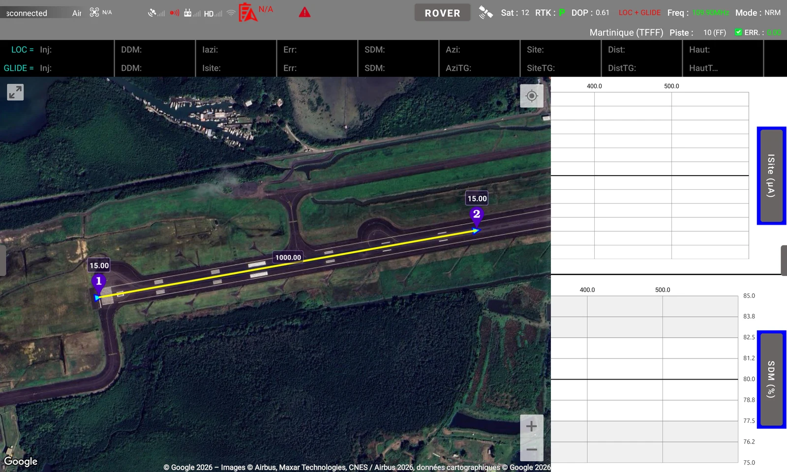
The map can be expanded over other interface panels for a clearer view of the site, drone and flight path. This example shows a path along the runway.
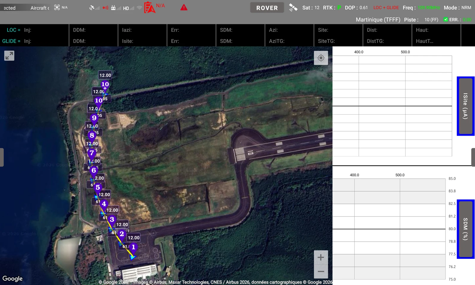
A second flight path example in the expanded map: calculated waypoints and the segments connecting them are displayed over the site.
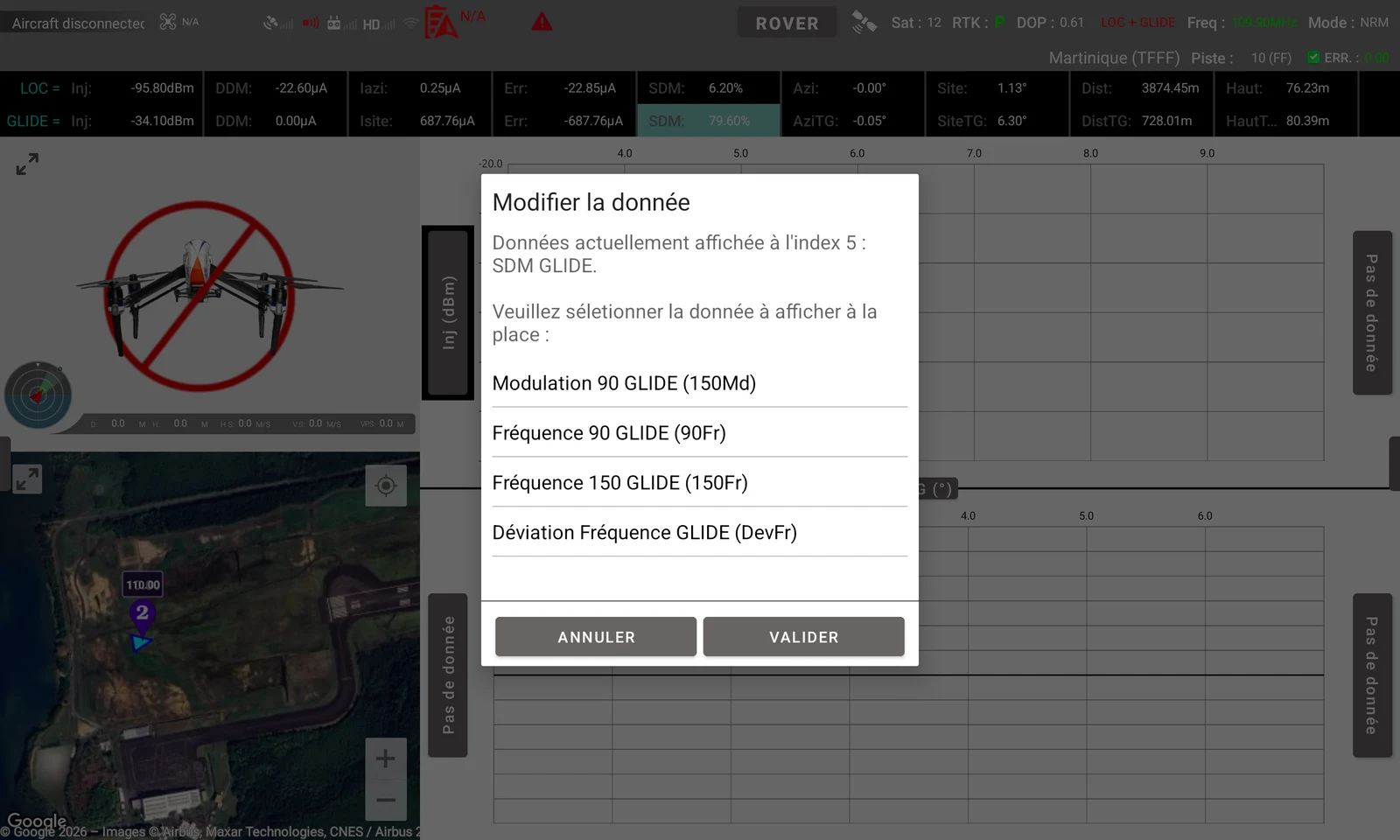
The data displayed in the toolbar and on the charts can be changed.
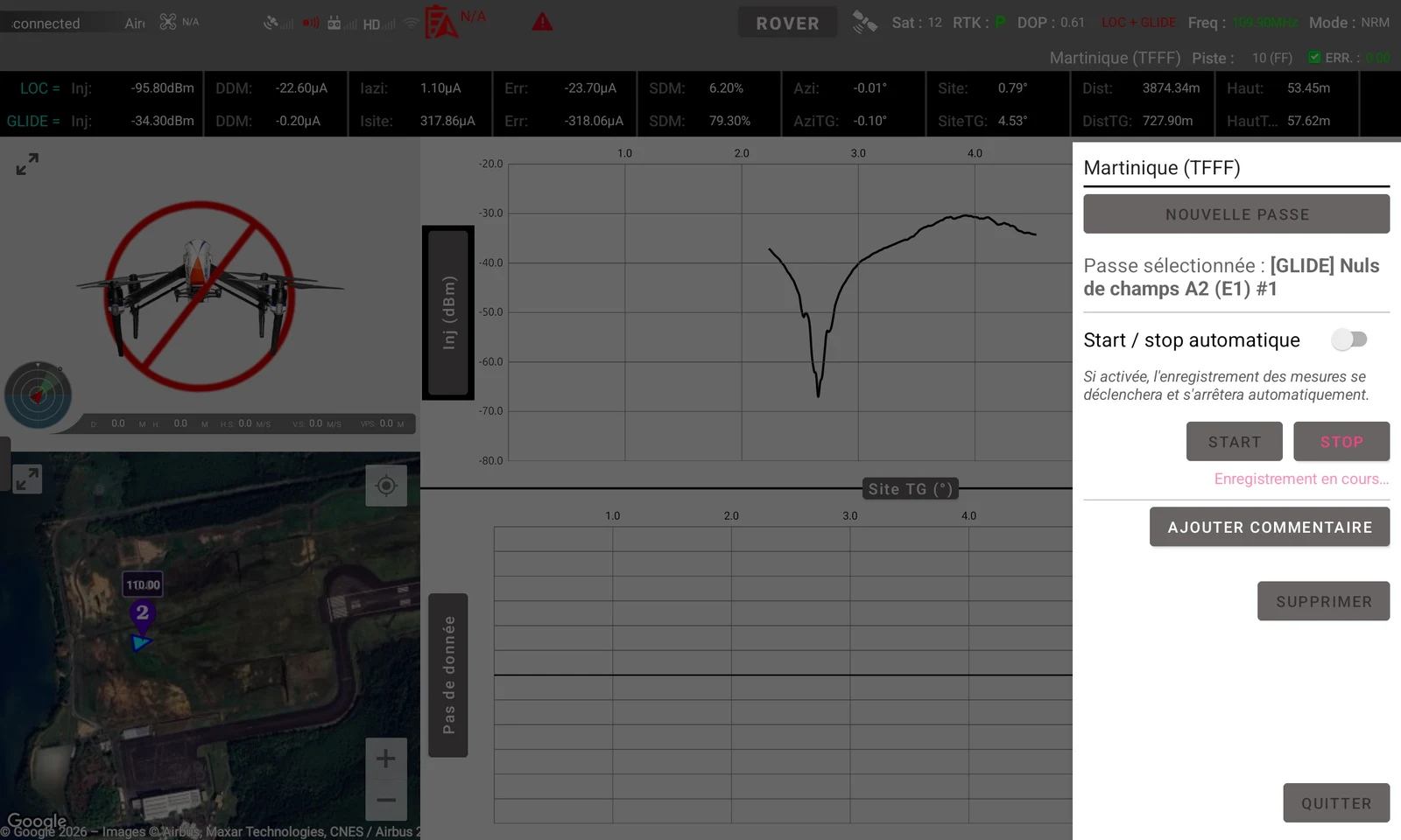
Pass management: selection, automatic start / stop triggered by the drone flying over, starting and stopping data recording, and adding comments.
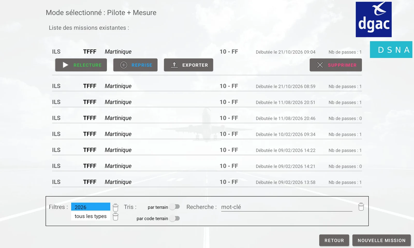
Mission search and filtering by year, type or site, with access to replay, resume and data export.
Application screenshots. The control views show a disconnected aircraft, so the FPV feed is not displayed.
03 / Functionality
The localizer (LOC) provides lateral ILS guidance, while the glide slope (GLIDE) provides vertical guidance. VOR provides an azimuth reference. UFIS combines radio measurements with the drone’s position to analyse them relative to the navigation aid under inspection.
DJI SDK
Receives the calculated flight path and provides mission commands, telemetry and an FPV video feed.
Bluetooth Low Energy
Pre-flight configuration of the measurement receiver and monitoring of its onboard services.
Bluetooth
GNSS reference configuration and reception of measurements relayed from the rover during flight.
The operator selects the site, runway and navigation aid to inspect. ILS and VOR reference data retrieved from the server provide the coordinates, orientations, frequencies and equipment characteristics. The mission retains its context, participants and configuration. Three operating modes support piloting only, measurement only, or combined piloting and measurement.
Using the inspection pass and selected flight pattern — orbit, half-orbit, radial, crossing, climb / descent or on-slope approach — UFIS computes the flight points in latitude, longitude and altitude. Distance, height, speed and altitude corrections adapt the route to the site. The flight path is then uploaded through the DJI SDK, with commands to start, stop and return home.
Before the mission, the rover connection allows the operator to set the reception mode, including LOC or GLIDE, and frequency, then check onboard services: BLE, GPS, SD card and receiver. The ground station is configured separately with its GNSS reference position.
UFIS includes an NTRIP client to obtain a centimetre-level reference position. It sends position data to the server as NMEA GGA messages, receives RTCM corrections and forwards them to the GNSS receiver. The operator monitors RTK solution quality, saves the resulting position and can transfer it to the ground station.
During flight, the ground station relays rover frames to the application. UFIS decodes navigation and positioning data, pairs NAV and GPS frames, performs calculations and updates numerical values and charts.
The operator selects the displayed quantities and chart axes: DDM, SDM, received signal level, error, azimuth, elevation angle or distance, depending on the inspection. The drone’s position on Google Maps and its FPV feed complete the view. Passes can be recorded with manual or automatic triggering and contextual comments.
Missions and measurements are stored locally. A recorded pass can be replayed at its original pace or at an increased speed to review how the charts and position evolved during flight.
The operator can invalidate measurement ranges directly on the charts and later reverse that decision. These measurements remain marked as invalid and are excluded from the relevant calculations, keeping disturbed or out-of-scope samples from distorting the analysis.
At the end of a pass, domain calculations use the retained measurements and installation characteristics. Depending on the inspection, they cover mean DDM error and SDM, LOC and GLIDE sectors, characteristic GLIDE elevation angles, VOR error, modulation depths and FM index.
Exports combine an XML file describing the mission, equipment and parameters with CSV files containing each pass’s data. Results can then be processed further while retaining their measurement context.
04 / Technology
UFIS is a native Android application written in Java. Its architecture separates communication, decoding, calculations, persistence and the interface, so each part can evolve with operational needs and hardware.
How a measurement moves through the application
A tablet interface built with Android components and direct integration with hardware SDKs and interfaces. Reception, computation and recording run in dedicated threads, separate from the user interface thread.
Separate managers handle classic Bluetooth and BLE. The serial communication library was adapted for binary exchanges; dedicated decoders handle measurement frames and receiver messages.
The DJI SDK handles communication with the drone. Google Maps provides mapping. GeographicLib supports geodesic calculations.
The embedded ObjectBox database stores all application data. No server connection is required to use the application.
A charting library integrated into the project and adapted to inspection workflows.
Crash reports and reported errors help diagnose issues encountered in the field. Separate development, test and release variants distinguish versions and their feedback.
This work combines an understanding of inspection passes and radio measurements with hardware communications, geodesy and real-time data processing. Connecting operational needs to their implementation is what I bring to a project.
Let’s discuss your project